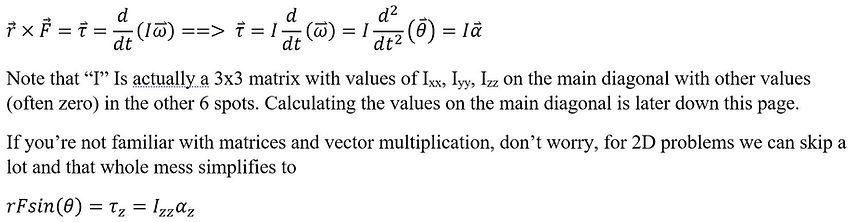
Moments and Torque
Torque is something we all deal with in our everyday lives, just as we can apply forces on objects to move them, we can apply torque to rotate them. Newton's laws are still the same but in the context of rotation, we use different variable names. Newton's 2nd becomes "Torque is equal to the time rate of change of angular momentum".
Torque uses the Greek letter tau "𝜏", Moments (I'll explain the difference later) use an uppercase M.
The greek letters alpha "α", omega "ω", and theta "θ" are variables used for angular acceleration, velocity, and position respectively; I'll go into more detail on the Rotation page on how these relate to linear kinematics.
the uppercase "I" is called the moment of inertia, and it's similar to mass, and covered in more detail later.
Note that the theta in "sin(θ)" is usually not the same as theta from angular kinematics, just another angle. For 2D problems, we can also drop the z subscripts, just note the direction of the vector is out of the page.
The first few questions involving torque may be statics problems like the ladder problem, in problems where alpha "α =0", and omega "ω=0" (ie nothing is moving) the word "torque" is replaced with "moment". It's not important why, it's just a different word for the same thing.
For questions like these, we know that the sum of moments is zero, as "α =0". This allows us to use another equation after the sum of forces equations. Remember we need at least as many equations as unknown variables.
The 1st step is to choose an axis to sum the moments around. This can be a hinge/axle, the center of mass, or any other point on the object. A rule of thumb is to find a point where the most lines of actions* of unknown forces pass through with as few knowns as possible.
The next step is to calculate the moment generated by each force, for 2D problems, we can use the simplified equation
r*F*sin(θ)=𝜏 (see diagram below)
where "r" is the distance between where the force is applied and the axis, "F" is the magnitude of the force, and theta is the angle between the vectors as shown in the diagram below. The sign of the torque is included in this equation.
Or alternatively, F*moment_arm is geometrically equivalent and is occasionally easier to use as shown in the ladder problem. However this does not show the sign of the torque, and the right-hand rule is needed to find which way it points.
*a line of action (LOA) is a line extending from both directions of a force vector (diagram below). The moment arm is the distance from the LOA to the axis, if this is zero, the moment is zero making the math easy.

The theta in this diagram MUST be "F" measured counterclockwise from "r".
If θ=90, sin(θ)=1, simplifying to 𝜏 = r*F (counter-clockwise twist)
Or, if θ=-90, sin(θ)=-1, simplifying to 𝜏 = -r*F (clockwise twist)
The last thing needed for a basic rotation problem is an understanding of moment of inertia (MOI).
The first step is knowing what axis the body rotates about; it's either going to be an axel of some sort, or a line through the center of mass depending on the context of the problem.
The most basic definition of MOI is the point mass formula (below). The MOI about an axis(P) is the sum of the mass(M) of each point mass, times the distance to the axis of rotation. For 2-D this is the distance to the center of mass (or axel) as the rotation axis is out of the page.

For solid 3D objects, Integrals can be used on the formula above (at about a calc 2 level) to produce general formulas for common shapes, assuming constant density.

For Compound shapes, its as simple as adding and subtracting MOI's. A hollow but not thin ball can be made by having the MOI of a sphere with the outer radius and the mass if it was solid, then subtracting the MOI of the missing part using the inner radius and the mass that would be there, assuming constant dencity.
These equations only apply for and object rotating about the axis shown in their respective picture, to move that axis, the parelell axis theorem used. Note that the old axis and new must be parelell, hence the name. For example, imagine holding a stationary bike wheel sideways at arms length. That can be decribed with the equation below, with the MOI around its own axis from the 2nd picture in the figure above, and the distance to the new axis as the length of your arms.

What this equation accounts for is that some of the hoop is further away from the new body axis increasing the difficulty to rotate and some is closer than the axel decreasing it. This shape would be a hard integral to get directly as each poind in the wheel is a diffrent distance from the body axis, but using the wheel around itself and then increasing the MOI with the theorem is simple.